In this Rktcr level editing tutorial, I will talk about the different kinds of level geometry available to you in the editor.
I will assume familiarity with the basics of Rktcr level editing.
As before, Rktcr full version 3.1 or newer is required. (While version 3.0 technically includes the editor, it fails to include a font used thereby.)
You can grab the level pack for this tutorial here.
The 'tut-geom' file is the starting point and the 'tut-geom-finished' is the finished level.
To make us of them, place the files in your ".rktcr/e_levels" folder, and load into the editor using f4.
Getting Started
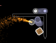
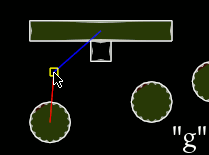
To start this tutorial, create and name a portal side ("start") and gem ("goal"), and save (f1) this as a new file.
I placed the portal and gem far apart because I anticipate adding lots of platform geometry, but you can always place them wherever and adjust it later.
(You could also use the starting point from the level pack, but it's probably quicker just to create it yourself.)
Types of Geometry
When you open the create prompt -- space, then backspace to delete that pesky space that appears the first time you open it for some reason -- you'll notice quite a few options:
We will be using all of the geometry-related options in this tutorial.
A brief overview:
Create Menu Options
poly -- create basic straight-line polygons. Workhorse geometry, covered in the basics. Reviewed below.arc/[->arc] -- create/[turn selected polygon into] arc-gon -- a polygon where each corner is replaced by a circular arc. Covered below.smooth -- create a subdiv-smoothed version the currently selected polyon. Covered below.dynamic -- create a dynamic (rigid body) version the currently selected polyon. Will be covered in a later tutorial.side -- create a portal side. See the basics.gem -- create a portal side. See the basics.paint, ppoly, ppoly* -- functions relating to level-set-painting geometry. Covered below.
Polygons
First, let's create some polygons; they are a good fundamental starting point, after all.
Additionally, the polygon editing controls remain useful for arcgons and smooths.
The controls for polygon creation are explained in detail in the basics, but to briefly review:
tab to toggle edit mode;
right-click to select, shift right-click to multi-select;
grab, scale, and rotate to move verts;
extrude and divide to create more verts;
x to remove verts.
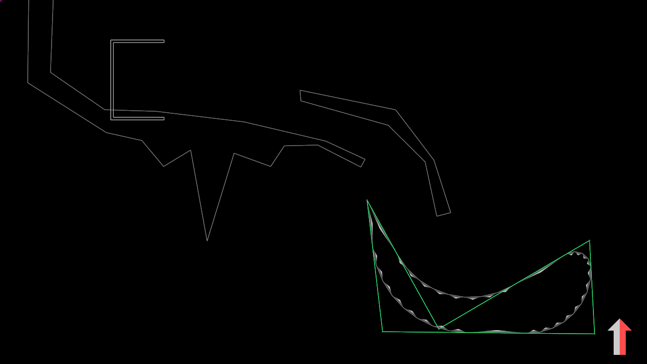
Arc-Gons
Now let's add some arc-gons to the level.
Create an arc-gon using the prompt and drop into edit mode (Space, arc, enter, tab).
All the polygon editing controls still work, but now apply to the "cage" around the actual arc-gon.
Additionally, left-click dragging will edit the radius associated with the selected corners.
When two adjacent corners's radii are longer than their edge, their radii are clamped.
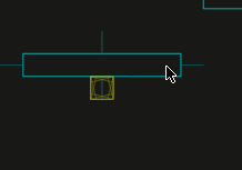
You can use this to precisely control the radius of a corner by placing a zero-length vertex some (fixed amount) of grid units away:
For example, in the above picture, the marked verts constrain the bottom left and upper right corners to have radii no greater than one grid unit and two grid units, respectively.
Converting Polygons to Arc-gons
One can also create arc-gons from polygons using the ->arc create command.
This will convert the current polygon into an arc-gon with zero-radius corners.
Here, I've used ->arc on a duplicate of the left ceiling polygon, then smoothed the internal vertices by going into edit mode, selecting them, and left-click dragging.
Really, you could just always work with arc-gons, but sometimes you don't want to worry about accidental left-click drags introducing small-radius corners.
Smoothed Polygons
Another way of creating polygons with smooth corners is to use the subdivision modifier.
These look "gooier" and a bit more organic to me than arc-gons.
Above -- from left to right -- I've created a poly and modified it a bit; then selected it and applied smooth (space, smooth, enter);
and, finally, dropped into edit mode (tab) to adjust the vertices more.
Note that duplicating a smoothed poly will give you a copy of the underlying cage, not the smoothed version, and pressing x on a smoothed poly will delete just the smoothing.
Level-Set Painting
Our level is coming along nicely.
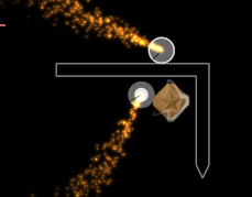
Let's finish it off by creating some geometry with level set painting.
Painting is a free-form method of specifying geometry;
you draw values into a grid, then extract contours of this potential field for use as level geometry.
To start, we'll need a canvas to paint on.
Create one by typing paint at the create prompt (i.e. space, paint, enter).
This will immediately drop into painting mode.
In painting mode, you add material with left-click and remove it with right-click.
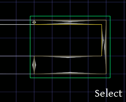
Red lines show the level geometry that (may) be created from the current paint.
The yellow line shows the outline of the canvas.
This will be automatically resized if you paint outside its borders.
The brush has two parameters, a radius (modify with shift-mousewheel) and a falloff distance (modify with ctrl-mousewheel).
The above image shows a few options. The falloff doesn't really do much unless you start painting a lot of positive and negative strokes, in which case it changes (a bit) how the generated geometry moves.
If you are painting large areas, the editor can bog down.
In this case, you can use up arrow and down arrow keys to adjust the painting grid resolution.
This is non-destructive (you can always switch back to an old resolution without a problem).
Note also that some simplification is always run on the output level geometry, so using finer grids may not actually change the number of vertices in your level.
Adding Paint-Polygons
If you have been playtesting your level, you will have noticed that your awesome paint doesn't actually appear in the game yet.
This is because you need to create paint polygons to pull information out of the paint.
The ppoly* command (i.e. space, ppoly*, enter) creates paint polygons for all contours in the currently selected canvas, while poly creates a polygon based on a seed point at your current mouse cursor.
Once created, paint polygons can be grabbed to offset them from their canvas positions, or deleted with x (useful for removing shards).
Additionally, changes in the original canvas will be reflected in the extracted outlines. This can be useful for minor edits to platform shapes.
Note that sometimes -- due to, e.g., topological changes in the canvas -- one can end up with multiple ppoly's for the same contour. This results in overlapping geometry and is generally bad news for your levels.
Wrapping up
In this tutorial, I showed you how to use Rktcr's four different types of level geometry:
basic polygons,
the somewhat smoother arc-gons,
the organic looking smooth modifier,
and the freeform paint-based geometry.
I find that each type of geometry lends itself to a different style of level -- as you'll notice in the game -- but that it can occasionally be useful to mix them up for specific situations.
Next Steps
Now that you are familiar with the various ways to create level geometry, it's time to add details and graphical polish.
In upcoming tutorials, I'll talk about adding dynamic objects and constraints;
working with disruptable platforms and gems;
adding bursts;
making your level prettier using style layers;
and giving folks a par time using claims.